What is a BC-221, and how to use it with a BA
Page started April 22, 2006. Last updated April 23, 2006.
A lot of the information I am going to present here is out on the web, in fact I am pretty sure all of it is. But several times recently I was asked, by people who know what a boatanchor is, how I could tell what frequency I was tuned to with a boatanchor. People, often used to digital readouts, look at the dials on many BAs and realize there just is not a great deal of accuracy represented there. When I say I use a BC-221 or an LM-18 some of them do not seem to understand. So, I decided one more web page needed to be created...as if there were not already enough...lol.
What is a BC-221 or an LM-XX?
The BC-221 and the Navy LM
series are heterodyne frequency meters. The basic units were developed in about
1941, and the contract for first production was let in 1942.
Many
different models and variations of each exist, but the basic function and
performance of all of them are the same. The BC-221 is around in both wood and
metal cases, while I think the LM series was always a metal case. The BC-221
normally ran on batteries, while many of the LM series came with an external
power supply that worked from various (model dependant) mains voltage. The LM
series has a selectable 500 Hz modulation capability that can make pre-tuning an
MCW or AM radio a little easier.
They consist of two high precision
variable frequency oscillators, one covering from 125 to 250 kHz and one
covering 2.0 to 4.0 MHz. Using these two ranges, and harmonics of each, the
units are capable of providing a stable known frequency anyplace from 125 kHz to
20.0 MHz. With interpolation of the results I have used them to 60.0 MHz before.
The basics are simple, if the low frequency VFO is tuned to 125 kHz,
then its 2nd harmonic is at 250 kHz, its 4th is at 500 kHz, and its 8th is at
1.000 MHz. So, the low band 125 to 250 kHz VFO gives you coverage from 125 kHz
to 2.000 MHz.
Now, the high frequency VFO (2.000 to 4.000 MHz), when
tuned to 2.000 MHz, yields known signals at 2.000, 4.000, and 8.000 MHz. The
16.000 MHz signal is also there, but on HF the designers decided to use
(document in this case, you will see what I mean later) the 5th harmonic above
16.000 MHz, so you tune the VFO to 3.200 MHz and above to get above 16.000 MHz.
It sounds a might confusing, but it is very simple to use.
What can a BC-221 do for me?
The BC-221 can be used for 3
basic radio transmitter or receiver frequency measurement task. They all assume
that you know roughly the frequency of the device you are testing/using. By this
I mean, with the frequency dials on many old radios you can tell about the freq
you are on, often to +/- 100 kHz or so, but you can't tell exactly where you
are. A few old boatanchors had readouts/displays that could confirm your
frequency to 5 kHz or better, but the majority could not. The BC-221 and friends
can tell you right where you are, sometimes to within a 100 Hz. In this day of
digital readouts to 1 Hz that may not seem like much, but as few as 20 years ago
having 100 Hz accuracy was outstanding.
1. - The BC-221 can measure the
operating frequency of a CW or AM transmitter. It was designed in a day when SSB
simply was not used, so it was not designed to support that mode. With a little
thought you can make it work for SSB also.
2. - The BC-221 can be used
to set a CW, MCW, or AM receiver to a desired frequency. You want to catch that
Voice of Africa schedule that starts at 1100 GMT on 17725, but that is still 10
minutes away? Use the BC-221 to set your boatanchor to the right frequency and
be ready for it. You don't have to wait until the transmission starts and tune
around hunting for it.
3. - The BC-221 can tell you what frequency you
are currently tuned to. You have tuned around 10.3 on the dial and picked up a
transmission in a language you don't recognize. Using the BC-221 you can find
out that the frequency is 10.330 MHz on the money, and that fact can help you
determine that this is most probably All India Radio. Without the actual
frequency it is much harder to tentatively ID a station if you can not hear or
understand the station ID.
These last 2 receiver usages are the ones I
am addressing right now with this page, later I may hit the transmitter
measurement. To understand why this ability is so important, it might help if I
show some example of boatanchor dials.
You can see from the tuning dial page that you should be able to tell within
500 kHz of where your BA is tuned, often much closer than that, say +/-20 or 50
kHz. You must have at least a rough idea of your frequency for the BC-221 or LM
series to be of much help to you, the better an idea you have the quicker the BC
can get you on freq or tell you your freq.
Introduction to the BC-221.
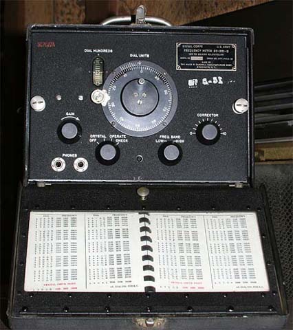
Although BC-221s come in a variety of cases, the faces and general layout are all pretty much the same. In this picture the cover is open, showing the main face and the calibration book. The calibration book is stored in the front cover and you must have the correct book for your specific BC-221.
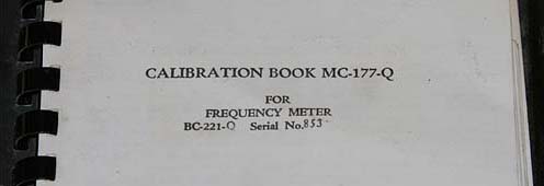
The ID plate in the upper right corner of the BC-221 has the model number and
serial number of the unit. The front cover of the calibration book has the same
information on it, model number and serial number. If you do not have the serial
number matched book for your specific BC-221 the book is just about useless to
you.
If you do not have the right book, all is not lost. With an
external frequency source or meter you can make your own book, but that will be
a pretty tedious process.
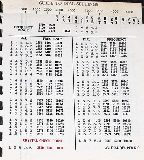
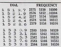
This is a typical page from the calibration book. Two columns per page. Each
column has a single row of typed entries under DIAL and at least three
(sometimes four) rows under FREQUENCY.
Across the top of the page you
will find the basic frequency ranges and the minimum and maximum dial positions
covered on that page.
At the bottom of the page will be the CRYSTAL
check points to be used anytime you reference this page. Each page has a unique
set of CRYSTAL check points. The frequency values of these check points are in
red print, the dial values are in the same type face as the DIAL entries
throughout the page.
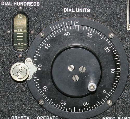
The silver "LOCK" knob must be turned counter clockwise to unlock the tuning
dial. Naturally, snugging the LOCK knob down clockwise locks the tuning dial. I
have run into one BC-221 that would not tune even when the LOCK was loosened,
this turned out to be a mechanical failure in the locking mechanism. I have no
idea if this is a common failure or not, I just throw it in here for general
information.
In the above picture the BC-221 dial is set to 1535.5. Lets
break down how this is determined.
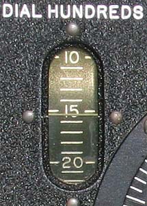
The hundreds place is read from the vertical window in the upper left corner
of the BC-221 front panel. Each division in this window is 100, every 5th mark
(or 500 units) is marked with a numaric value, 5, 10, 15, 20, etc, from 0 to 50.
The pointer for this window in our example is between the labeled "15" mark and
the next unlabeled (16) mark. Making our value more than 1500 and less than
1600, or 15XX.X. The next step is to fill in the X's.
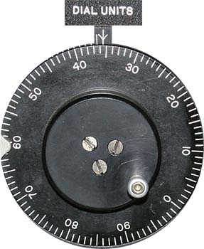
The tens and ones place are read from the main round spinning dial of the
BC-221. At the center top of this dial is an unmoving pointer. Around the dial
are 100 increments, with each 10, from 0 to 90, marked. In our example the
pointer is indicating between the labeled 35 and unlabeled 36 mark. When
combined with the 15XX.X we got in the previous step, we now have 1535.X. One
more X to fill in.
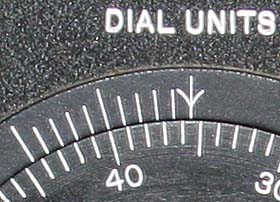
Reading the tenths position is a combination of the outer unmoving vernier
scale (with its 11 unmarked hash marks, 0.0 to 1.0, note that the 0, 5, and 10
marks are taller than the others), and the hash marks (but not values) on the
inner moving dial. In the picture above note that the pointer (downwards
pointing arrow) is between two marks, the marked 35 and the unmarked 36. This
was used in the last step to determine the 10's and 1's place. What is important
is the pointer (which is the X.0 mark) is NOT lined up with a hash mark on the
inner scale. On the unmoving outer scale we go to the next mark to the left (the
X.1 mark), it also is not lined up with an inner mark. Neither are the next 3
outer marks. We must go to the fifth outer mark (X.5) to find an inner and an
outer hash mark exactly aligned. The inner mark is the 40, but that value is not
important, only that this is the first aligning set of marks. This gives us a
tenths value of 5. If the third mark was lined up the tenths value would be 3,
if the eighth lined up it would be 8, and so on.
Making our indication
1535.5 for all of the above combined steps. It sounds like a pain to do, but
after just a little practice it is very quick and easy.
The value read
from the dial will be used with the information in the log book to determine
what frequency the BC-221 is indicating.
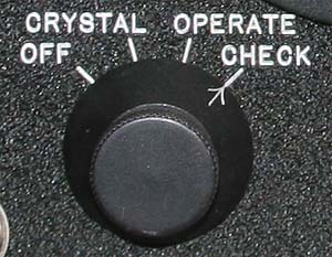
The main control knob on the BC-221 has four positions, OFF, CRYSTAL,
OPERATE, and CHECK. Any position besides OFF keeps the tubes warm as long as
headphones are plugged in. Like any hollow state device you must allow the
BC-221 to warm up for a while before you use it, I like to have it on at least
10 minutes before first measurement, longer is better. Failure to do so will
result in greater drift during the time you measure, and thus less accuracy.
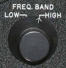
The BC-221 FREQ. BAND selector has two positions, LOW and HIGH. The LOW band provides measurement capability from 125 kHz to 2.000 MHz. The HIGH band works from 2.000 MHz up to at least 20.000 MHz.
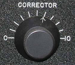
The CORRECTOR control is used to adjust the BC-221 dial to be correct in
reference to a fixed crystal oscillator source. This is what provides the VFO's
and their dials with the accuracy required over a broad range with simple
circuitry.
To perform the CRYSTAL check you must have a rough idea of
your intended frequency.
1 - Find your intended frequency in the
calibration book. Note the CRYSTAL check point in red at the bottom of the page,
the important number is the DIAL setting.
2 - Turn the main control knob
to the CHECK position and the DIAL to the number indicated at the bottom of the
page for the CRYSTAL checkpoint.
3 - Listen to the headphones and adjust
the CORRECTOR control. You want to achieve zero beat in the headphones.
4 - Turn the control knob to OPERATE. You are now ready to determine or
set your exact radio frequency. Each time you go to a new page in the
calibration book you must perform a CRYSTAL check, I would recommend you do so
after a period of time also, even if you stay on the same page. With time the
BC-221 will drift a little in frequency, your CRYSTAL check is how you negate
this drift.
As you can see in the above example, any given dial position can be more than
one frequency. Between three and four are what are normally documented in the
calibration book, but there are actually even more.
To set the frequency
2.580, 5.160, or 10.320 MHz is simple, just adjust the dial to 1530.9, and you
are there.
But how do you set a frequency not listed on the page, maybe
something like 10.325 kHz? 10.324 and 10.328 MHz are both listed but not 10.325
MHz. Getting "between" the listed frequencies is pretty easy also.
1 -
Pick the two closest frequencies on each side of the desired frequency, in our
example 10.324 and 10.328 MHz. Their dial settings are 1533.1 for 10.324 MHz and
1535.3 for 10.328 MHz.
2 - Subtract the lower dial reading from the
upper. In this case 1533.1 from 1535.3. This leaves 2.2 dial units between the
two points.
3 - The subtract the lower frequency from the upper. 10.324
from 10.328 MHz leaves 4 kHz.
4 - Divide the number of dial units by the
frequency span, in our example 2.2 units divided by 4 kHz. This leave .55 dial
units per kHz. Naturally, we know that our dial is only good for tenths of a
unit (x.1) and not hundredths (x.01), so we may have to round off a bit to make
things work.
5 - Subtract the lower closest frequency form the frequency
you want to be at, in our case the listed 10.324 from our desired 10.325. This
leaves a difference of 1 kHz.
6 - Multiply the difference frequency
times the dial units per kHz. In our example 1 kHz times .55 dial units, or a
total of .55 dial units.
7 - Add the calculated number of dial units to
the lowest documented dial units, in this case .55 added to 1533.1, for a new
dial setting of 1533.65 being equal to 10.325 kHz. Our dial does not do
hundredths, so we must round off to the closest tenth, or 1533.7 on the dial.
This would actually leave us about 100 Hz high in frequency, but close enough.
It seems complicated, but again, just like reading the dial, after a few
goes at it you can be very quick.
Some boatanchor dial examples.
E-mail me at: mailto:T_O_K_E_N_@hotmail.com